VMWare ESXI – Move Management Interface

Moving the management interface turned out to be more daunting than I had imagined. By design this is not possible to do within the GUI that is accessed over HTTP. Instead you are required to do this via the CLI. I assume local shell access is required, but it may be possible to do this over SSH. Ensuring you have physical access is critical in the event you make a mistake and lose network access to the management interface.

By default it seems the management interface is associated with the vmnic0 interface. This is fine until you realize that guest VM’s may also share the vmnic0 interface. This can happen when you do not create any additional vSwitches beyond vSwitch0 and you subsequently create virtual machines that are using vSwitch0.

I would consider it a best practice to isolate the management interface so that it does not share a physical nic with any other vm guests. Doing so will allow you to isolate the management interface by connecting it to a separate switch port and vlan.

Some folks go so far as to air gap the management interface, which I will do too, but only after I have managed to isolate the management interface from all other traffic.

To begin, I access the web based gui and identify a vSwitch that is not currently used and I give it a unique name, I will reference this later in the code examples. In my case vSwitch0 was used by many guest VM’s and the management interface. In addition vSwitch1 and vSwitch2 were configured to utilize vnic2 and vnic3 respectively.  Because I am using a 4 port ethernet adapter I confirmed vSwitch1 was unutilized and I renamed it to vSwitch-MGMT.

As you can see from the next image, I am unable to update the Management Network port group settings to utilize a different virtual switch. Note, the example reflects my changes, but the fact remains that you are prevented from making the change via the GUI.

The ESXi shell is not enabled by default, for good reason, so you first must have physical access to the server and login by clicking F2. The move through the menu and access


  1. Create new portgroup on

ICMP Ping test using Arduino

Sounds easy right? Not really.

The Arduino Uno requires a shield in order to access a wired Ethernet network, such as the SunFounder clone on Amazon that resembles the genuine Ethernet Shield 2 from Arduino.cc.

First of all, the scripts will write to the serial monitor so that I may see if the icmp pings are successful. Remember to close the serial monitor before you attempt to upload any code, you will receive errors indicating the com port is busy and that access is denied.  In other words, the serial monitor and the upload action are using the same COM port to communicate, but only one may be used at a time.

Moving on, I located the Arduino-Ping project, written by Blake Foster and hosted on Github.  In order to incorporate his library I must build a new folder within the Arduino project called libraries, within that an additional folder sharing the same name as the .cpp/.h file, in this case ICMPPing.

After loading his example named Ping.ino I was met with many errors of the following variety. Those indicated to me that the methods defined in the Ping library were calling undefined methods in the Ethernet library.

C:\arduino-1.8.8\portable\sketchbook\libraries\icmp_ping\ICMPPing.cpp:184:11: error: 'class W5100Class' has no member named 'send_data_processing'

     W5100.send_data_processing(_socket, serialized, sizeof(ICMPEcho));

           ^

C:\arduino-1.8.8\portable\sketchbook\libraries\icmp_ping\ICMPPing.cpp: In member function 'void ICMPPing::receiveEchoReply(const ICMPEcho&, const IPAddress&, ICMPEchoReply&)':

C:\arduino-1.8.8\portable\sketchbook\libraries\icmp_ping\ICMPPing.cpp:207:19: error: 'class W5100Class' has no member named 'getRXReceivedSize'

         if (W5100.getRXReceivedSize(_socket) < 1)

After a bit of contemplation and searching for answers I learned that the Ethernet library, version 2, broke Blake’s ICMP-Ping library. To my relief, I found a thread on the Wiznet forum which documented that the Arduino Ethernet library versions 1.0.0 through 1.0.4 worked well with Blake’s code.

So, I returned to the Arduino IDE and accessed the menu option Sketch > Include Library > Manage Libraries. 

Once in the library manager I search for the Ethernet library from the left pane. In the results observe you can assign what version you would like to use with a project. In my event I switched to 1.0.4, after doing so the code compiled.

But, it was still not working to my satisfaction. The pings were failing and I noticed that the shield was attempting to resolve the IP using ARP. However the ARP requests were asking for a MAC address for the assumed gateway.

Blake’s example includes the IP 192,168.2.177, which is a network with a 24 bit network mask.  I knew immediately I would encounter errors until I adjust that.

So, as I continue developing this solution I turn my attention toward configuring a network mask that accurately reflects our network.

Needless to say I found plenty of wrong examples suggesting that the myDns attribute was instead dns. Knowing better, I checked the Arduino Ethernet class reference and there I discovered the right syntax. I had to then modify Brandon’s script in order to initialize the Ethernet object while using the additional myDns and gateway parameters.

As you can see from the image above, these few changes led to a script that worked for us. In the next episode I will present the code used to control relays that will operate a Simplex Grinell 4906-9151 Speaker Strobe.

Chrome Default Profile

You can adjust registry settings so that Chrome starts with a specific user profile. To begin, open regedit and navigate to HKEY_CLASSES_ROOT\ChromeHTML\shell\open\command

Modify value of Default key

Original

"C:\Program Files\Google\Chrome\Application\chrome.exe" --single-argument %1

After my changes

"C:\Program Files\Google\Chrome\Application\chrome.exe" --profile-directory="Default" --single-argument %1

Note, in the example above, I am not passing the full file path to the profile folder, instead I simply list the profile specific folder name.

Reference: https://superuser.com/questions/109589/make-google-chrome-with-specific-user-profile-as-default-browser

Start Chrome with specific user profile

Running chrome.exe from CMD will fail so be sure to include it in the $PATH variable
C:\Program Files\Google\Chrome\Application

chrome.exe --args --profile-directory=Default

You can find the profiles located in the user home directory
%USERPROFILE%\AppData\Local\\Google\Chrome\User Data\

As you can see, I have a few profiles to choose from. Once I know which one to use, I will supply the directory name to the –profile-directory option.

chrome.exe --args --profile-directory="Profile 3"

In my situation I selected the Default profile that was signed in the with the specific Google account I had need to work with.

chrome.exe --args --profile-directory="Profile 3"

Palo Alto – Security Rule Count

Review and clear hit count for specific security rule within a Palo Alto firewall.

show rule-hit-count vsys vsys-name vsys1 rule-base security rules list 'Rule Name'

Rule Name Hit Count Last Hit Timestamp Last Reset Timestamp First Hit Timestamp Rule Create Timestamp Rule Modify Timestamp
 ---------------------------------------------------------------------------------------------------------------------------------------------------------------------------------------------------------------
 RuleName 247738490 Mon Feb 21 11:24:47 2022 - Wed Jul 17 08:43:59 2019 Wed Jul 17 08:43:59 2019 Fri Jun 4 15:29:27 2021

Vsys: vsys1
 Rulebase: security

clear rule-hit-count vsys vsys-name vsys1 rule-base security rules list 'Rule Name'

Show ARP Table on Unifi Switch

To begin, we will need to open putty and create a new SSH connection with the switch.

Once logged into the switch we can must visit the edgeos CLI, accessible on port 2222 of localhost
 telnet 127.0.0.1 2222

Now you can list the arp table with the following command
show mac-addr-table

You can expect results as shown below
 1 10:98:C3:92:CF:39 0/49 49 Learned
 1 14:58:D0:5D:F2:F6 0/24 24 Learned
 1 16:A9:A2:34:29:97 0/49 49 Learned

Determine Authenticating Domain Controller

Back when Server 2003 was the new hot thing, password policy could only be set at the domain level. Since then, Password Security Objects were introduced in Active Directory, beginning with Server 2008. PSO are like GPO’s and can be scoped to a specific OU, user, or group. In order to use PSO, ensure domain policy as defined in a GPO has been cleared out first.
To learn more about PSO, read the following: Fine Grained Password Policy

I was troubleshooting an issue where a user was unable to update their password, despite meeting password complexity requirements. Evidently, the minimum password age was set to 30, so they were prevented from creating a new password, in that 30 day window, until I changed the min. password age to 0.

Another few commands I found useful during this project were:

Determine computer / server DC using nltest

nltest /dsgetdc:<domain>

List all DC’s

nltest /dclist:<domain>

Determine server used for user authentication:

echo %logonserver%

Build a weather station using esp8266, ssd1306, dht22

In this post I present an overview building a weather station I could place in my garden, hoping to monitor temperature and humidity. I’ll use a esp8266 NodeMCU WiFi module to stream this data to Losant, an IOT platform. We’ll also display these readings on a ssd1306 0.96″ OLED screen. The temperature and humidity are observed using a DHT22 sensor module.  Eventually I’ll add moisture probes that will be used to trigger relays used to active a sprinkler during the hot, dry months of July and August in Wisconsin. Other goals include adding sensors to monitor rainfall, wind speed, and wind direction.

My code went through a few iterations to start. I wanted to take readings from the DHT22 and put them on the console monitor. I also printed some simple banner to the OLED display as well. At one point I found an i2c scanner to ensure my laptop could see the esp8266. In the end, I combined code with the examples from Losant to stream sensors readings to the cloud over WiFi and to a 128×64 OLED.

i2c Scanner

// --------------------------------------
// i2c_scanner
//
// Version 1
// This program (or code that looks like it)
// can be found in many places.
// For example on the Arduino.cc forum.
// The original author is not know.
// Version 2, Juni 2012, Using Arduino 1.0.1
// Adapted to be as simple as possible by Arduino.cc user Krodal
// Version 3, Feb 26 2013
// V3 by louarnold
// Version 4, March 3, 2013, Using Arduino 1.0.3
// by Arduino.cc user Krodal.
// Changes by louarnold removed.
// Scanning addresses changed from 0...127 to 1...119,
// according to the i2c scanner by Nick Gammon
// http://www.gammon.com.au/forum/?id=10896
// Version 5, March 28, 2013
// As version 4, but address scans now to 127.
// A sensor seems to use address 120.
// Version 6, November 27, 2015.
// Added waiting for the Leonardo serial communication.
//
//
// This sketch tests the standard 7-bit addresses
// Devices with higher bit address might not be seen properly.
//
 
#include <Wire.h>
 
 
void setup()
{
 
 Serial.begin(9600);
 while (!Serial); // Leonardo: wait for serial monitor
 Serial.println("\nI2C Scanner");
}
 
 
void loop()
{
 byte error, address;
 int nDevices;

Wire.begin();
 
 Serial.println("Scanning...");
 
 nDevices = 0;
 for(address = 1; address < 127; address++ )
 {
 // The i2c_scanner uses the return value of
 // the Write.endTransmisstion to see if
 // a device did acknowledge to the address.
 Wire.beginTransmission(address);
 error = Wire.endTransmission();
 
 if (error == 0)
 {
 Serial.print("I2C device found at address 0x");
 if (address<16)
 Serial.print("0");
 Serial.print(address,HEX);
 Serial.println(" !");
 
 nDevices++;
 }
 else if (error==4)
 {
 Serial.print("Unknown error at address 0x");
 if (address<16)
 Serial.print("0");
 Serial.println(address,HEX);
 } 
 }
 if (nDevices == 0)
 Serial.println("No I2C devices found\n");
 else
 Serial.println("done\n");
 
 delay(5000); // wait 5 seconds for next scan
}

128×64 OLED Test

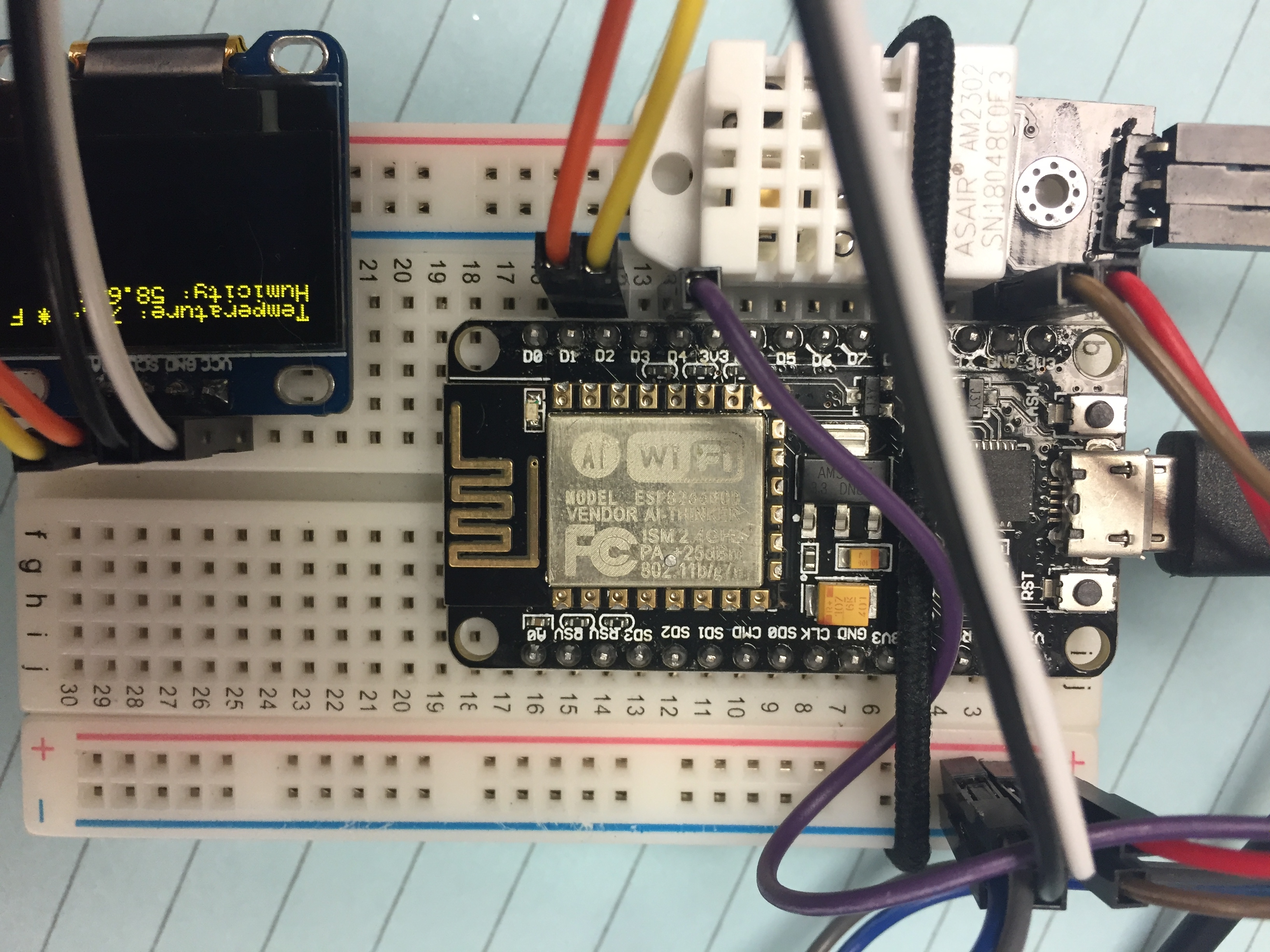
The small display relies on the i2c communication protocol, as does the DHT22, making connections to the esp8266 very straightforward. The display has 4 pins: 3-5v logic, ground, serial clock (SCL) and serial data (SDA).

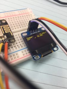
It’s essential to connect SCL,SDA pins of oled display to pins on esp8266 marked D1 and D2.

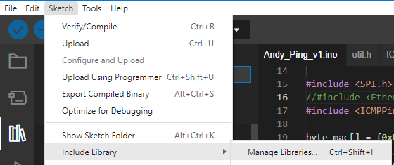
The key is to load the Adafruit_GFX and Adafruit_SSD1306 libraries.

#include <SPI.h>
#include <Wire.h>
#include <Adafruit_GFX.h>
#include <Adafruit_SSD1306.h>

#define OLED_RESET LED_BUILTIN //4
Adafruit_SSD1306 display(OLED_RESET);

#if (SSD1306_LCDHEIGHT != 64)
#error("Height incorrect, please fix Adafruit_SSD1306.h!");
#endif

void setup() {
 display.begin(SSD1306_SWITCHCAPVCC, 0x3C);

// Clear the buffer.
 display.clearDisplay();
 display.display();

display.setTextSize(1);
 display.setTextColor(WHITE);
 display.setCursor(0,0);
 display.println("Hello from:");
 display.println("http://arduino-er.blogspot.com/");
 display.display();

}

void loop() {
 // put your main code here, to run repeatedly:

}

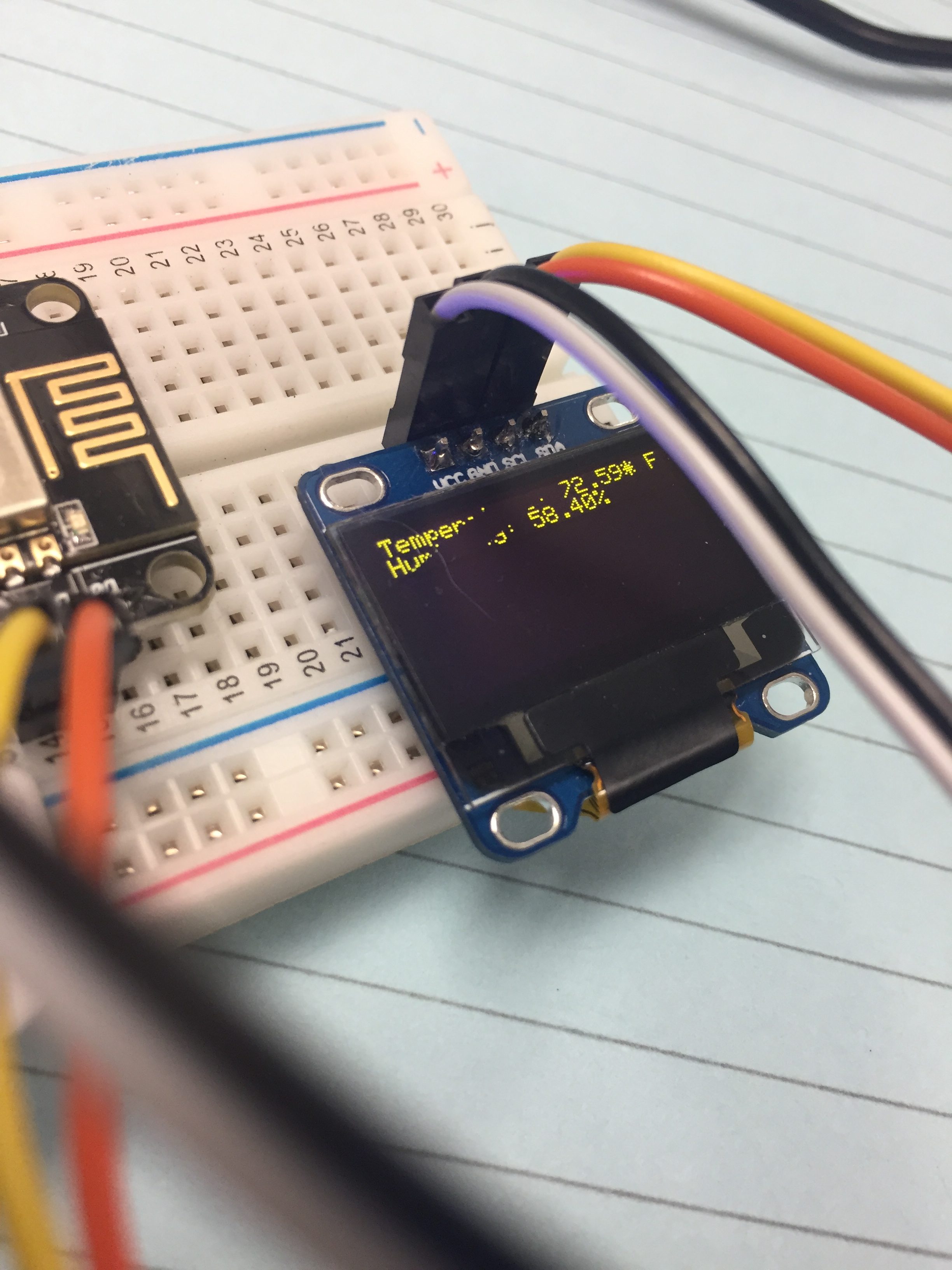
Read DHT22 and display on OLED – Borrowed from Losant

/**
 * Example for reading temperature and humidity
 * using the DHT22 and ESP8266
 *
 * Copyright (c) 2016 Losant IoT. All rights reserved.
 * https://www.losant.com
 */

#include "DHT.h";
#define DHTPIN 2 // what digital pin the DHT22 is conected to
#define DHTTYPE DHT22 // there are multiple kinds of DHT sensors
DHT dht(DHTPIN, DHTTYPE);

//#include <Wire.h>
#include <Adafruit_GFX.h>
#include <Adafruit_SSD1306.h>
#define OLED_RESET LED_BUILTIN //4
Adafruit_SSD1306 display(OLED_RESET);

void setup() {
 Serial.begin(9600);
 Serial.setTimeout(2000);

/*display.setTextSize(1);
 display.setTextColor(WHITE);
 display.setCursor(0,0);
 display.println("Temperature:");
 display.println("Humidity");
 display.display();*/
 
 // Wait for serial to initialize.
 while(!Serial) { }

Serial.println("Device Started");
 Serial.println("-------------------------------------");
 Serial.println("Running DHT!");
 Serial.println("-------------------------------------");

}

int timeSinceLastRead = 0;
void loop() {

// Report every 2 seconds.
 if(timeSinceLastRead > 2000) {
 // Reading temperature or humidity takes about 250 milliseconds!
 // Sensor readings may also be up to 2 seconds 'old' (its a very slow sensor)
 float h = dht.readHumidity();
 // Read temperature as Celsius (the default)
 float t = dht.readTemperature();
 // Read temperature as Fahrenheit (isFahrenheit = true)
 float f = dht.readTemperature(true);

// Check if any reads failed and exit early (to try again).
 if (isnan(h) || isnan(t) || isnan(f)) {
 Serial.println("Failed to read from DHT sensor!");
 timeSinceLastRead = 0;
 return;
 }

// Compute heat index in Fahrenheit (the default)
 float hif = dht.computeHeatIndex(f, h);
 // Compute heat index in Celsius (isFahreheit = false)
 float hic = dht.computeHeatIndex(t, h, false);

Serial.print("Humidity: ");
 Serial.print(h);
 Serial.print(" %\t");
 Serial.print("Temperature: ");
 Serial.print(t);
 Serial.print(" *C ");
 Serial.print(f);
 Serial.print(" *F\t");
 Serial.print("Heat index: ");
 Serial.print(hic);
 Serial.print(" *C ");
 Serial.print(hif);
 Serial.println(" *F");

// Clear the buffer.
 display.begin(SSD1306_SWITCHCAPVCC, 0x3c); // initialize with the I2C addr 0x3D (for the 128x64)
 // Clear the buffer.
 display.clearDisplay();
 display.display();
 
 //display.clearDisplay();
 //display.display();

display.setTextSize(1);
 display.setTextColor(WHITE);
 display.setCursor(0,0);
 //char temperature[5] = "";
 //dtostrf(hif, 3,1,temperature);
 String buf;
 buf += F("Temperature: ");
 buf += String(hif,2);
 buf += " F";
 display.println(buf);
 buf="";
 buf += F("Humidity: ");
 buf += String(h,2);
 buf += "%";
 //char humidity[5] = "";
 //dtostrf(h, 3,1,humidity);
 display.println(buf);
 display.display();

/* //Send Temp & Humidity to OLED
display.clearDisplay();
display.display();
 display.setTextSize(1);
 display.setTextColor(WHITE);
 display.setCursor(0,0);
 display.println("Temperature: *F");
 display.println("Humidity: %");
 display.display();*/
/*
 display.setTextSize(1);
 display.setTextColor(WHITE);
 display.setCursor(0,0);
 display.println("");
 display.setTextSize(2);
 display.println("Temperature: F");
 display.println("Humidity: %");
 display.display();
 */

timeSinceLastRead = 0;
 }
 delay(100);
 timeSinceLastRead += 100;
}

Losant Example

The Whole Kaboodle


Reset Computer Machine Password

Occasionally I’ll receive a report that domain users cannot login to a specific laptop, citing an error message “The trust relationship between this workstation and the primary domain failed.” It’s worth noting that although domain accounts cannot be used to sign in, local computer accounts may still be used.

Microsoft has issued two solutions to this problem. One solution involves logging into the PC using a local computer account and taking the PC off the domain, reboot, sign in again with local account, and once more join the laptop to the domain. This works, but it’s slow.

A better solution that takes less time requires us to use a powershell cmdlet. Again, login to the PC with a local account and issue the following in Powershell running with Administrative rights.

$creds = Get-Credential
Reset-ComputerMachinePassword -Credential $creds -Server dc1.domain.edu

The first command will display a prompt that will collect username and password that will be used to execute the next cmdlet. Be aware you must provide an account with Domain Admin privileges. After execution, log out. You may now log in again using domain accounts.

Youtube Restricted Mode

Youtube is a great resource for learning and entertainment. However, it can also be a great distraction too. In addition to that, there is a considerable amount of content that many would find questionable at best. In order to filter the most offensive content we can employ Youtube restricted or moderate restricted mode.

Although there are many ways to accomplish this, including setting domain wide user policies in Google admin console, this will only target folks who are using their Google profile that was provided by their employer. To ensure we apply this policy to everyone, we can use DNS redirection.

It’s worth noting some articles suggested creating a DNAME record in each zone that points to either restrict.youtube.com or restrictmoderate.com. In my experience this failed. I had success creating an A record instead for each zone.

This article makes the assumption you administer a Windows based DNS server. To begin, create 5 new forward lookup zones:

www.youtube.com

m.youtube.com

www.youtube-nocookie.com

youtube.googleapis.com

youtubei.googleapis.com

Within each zone, create a new A record. Leave the Name field blank and enter 216.239.38.120 in the IP Address field. Use 216.239.38.120 for restricted mode, or 216.239.38.119 for moderate restricted mode.

After having done this you should be able to open a browser and verify the changes by heading to https://www.youtube.com/check_content_restrictions.